Global Auto Parts & Accessories Marketplace

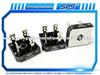
SPS 1000V Bridge Rectifiers KBPC5010 Working Principle
- Application: ALL
- Market Type:After Market
- EXW Price: USD 0.01
- Other Price Term: FOB,CNF
- Payment Terms: T/T
- Samples: Free
- Minimum Order: 1000Piece/Pieces
Quick Details
- Place of Origin:
CHINA
- Samples:
Free
- Delivery Time:
20-40DAYS
- Packing:
BULK
- Delivery Port:
SHANGHAI
- Export Ratio:
81% - 90%
- OE Experience:
No
Product Name:SPS 1000V Bridge Rectifiers KBPC5010 Working Principle
SPS 1000V Bridge Rectifiers KBPC5010 Working Principle
Application
ALL
Product Description:
Special Sun A·H·M TechnologyShanghaiCo.,Ltd.
SPS - ISO Factory for SMD and Through-hole Diodes and Rectifiers Since 2000
KBPC5010 is 50A, 1000V (1, 2, 3, 4, 5, 6, 7 or 005, 01, 02, 04, 06, 08, 10 respectively represent the voltage range of 50V, 100V, 200V, 400V, 600V, 800V, 1000V).
The working principle and application of bridge rectifier KBPC5010:
The purpose of bridge rectifier KBPC5010 is to convert alternating current into direct current. What is the working principle of the bridge rectifier in the circuit?
The rectification in the bridge rectifier is a term. It completes its work through the principle of unidirectional conduction of the diode. To put it simply, the diode is unidirectional, which is forward conduction and reverse cutoff. In other words, the diode only allows its positive pole to enter positive electricity and its negative pole to enter negative electricity. The diode only allows current to pass in one direction, so when it is connected to an AC circuit, it can make the current in the circuit flow only in one direction, the so-called "rectification". Among them, two diodes are half-wave bridge rectifiers, and four are full-wave bridge rectifiers.
1. Rectifier circuit: use a bridge rectifier with unidirectional conductivity, which can also be called a bridge rectifier stack. Convert the 50HZ alternating current in the circuit whose direction and size are changed into direct current with the same direction but still pulsating in size.
2. Filter circuit: Utilizing the nature of the energy storage element that the voltage at both ends of the capacitor C cannot change suddenly, connecting the capacitor C in parallel with the load RL of the rectifier circuit can filter out most of the AC components in the output of the rectifier circuit, thereby obtaining a relatively smooth Direct current. In low-power rectifier circuits, capacitor filtering is often used.
3. Power transformer: transform the AC voltage of the grid into an AC voltage that meets the requirements, and the AC voltage can be rectified to obtain the DC voltage required by the electronic equipment.
4. Voltage stabilizer circuit: When the grid voltage or load current changes, the amplitude of the DC voltage output by the filter circuit will also change accordingly. Therefore, the function of the stabilizer circuit is to stabilize the DC voltage after rectification and filtering. In the low-power DC power supply, several common rectifier bridge circuits are single-phase half-wave, full-wave, bridge and three-phase, among which there are both AC and DC.
By using a secondary winding of the transformer and the rectifier bridge, the load of the rectifier circuit can have pulsating DC voltage and current in the same direction within the positive and negative half cycles of the AC power supply.

Check the best offer with SPS, a professional factory of diode rectifiers, bridge rectifiers, transistors etc.
According to the modelsView More
Supplier Details
You May Like:
-

-
Rectifier F00M123200 230075 IBR201 9120217 0389033 ...
Application: Alternator
OEM No: F00M123 ...
-
-
SPS BR3510 Bridge Rectifier Diode 35A 1000V Single ...
Application: audi, BMW, BENZ, ...
-

-
SPS 50A 1000V Glass Passivated Single Phase Bridge ...
Application: ALL
-

-
SPS 10A 600V Glass Passivated Single Phase Bridge ...
Application: ALL
-

-
Rectifier 0216001381 136312 INR717
Application: Alternator
OEM No: 0216001 ...
-

-
Mercedes Truck Solenoid Valve, Shift Cylinder 945 ...
Application: Mercedes-Benz Se ...
OEM No: 945 260 ...
-

-
Truck Rectifier (For Car Bus Truck For Benz 001154 ...
Application: benz
OEM No: 0011542 ...
-

-
VALEO RECTIFIER 105252 FOR RENAULT
Application: RENAULT
OEM No: 105252
-

-
Car Auto Rectifier, Alternator Rectifier D528
Application: Alfa romeo
OEM No: Dn528
Related Product Tags:
alternator rectifier , alternator rectifiers , bridge rectifier , Diode Bridge Rectifier , Phase Bridge Rectifier , diodes , magnetic ballast , rectifiers , rectifier , Junction Rectifier , HITACHI Rectifier , MISUBISHI Rectifier , NEVILLE Rectifier , MOTOROLA Rectifier , LUCAS Rectifier , Compliant Rectifier , Diode Rectifier , DELCO Rectifier Didn't find what you are looking for?
Please send us Your Search Requirement, or you can Post a Buying Lead,
suppliers may contact you actively.
Please send us Your Search Requirement, or you can Post a Buying Lead,
suppliers may contact you actively.